Sunday, February 24, 2008

Assembling the cabinet, speaker grill and marquee!

During the past week and a half I assembled most of the cabinet. After test-fitting the panels with clamps, I bore little holes from the inside of the cabinet (where I had drawn the lines) to guide the screws. Then I applied the woodglue, assemble the panels again with clamps and then drill another hole through the panel but this time from the outside of the cabinet with the countersink drill bit and then put the screws in. Worked great! But just make sure you don't put the screws to close to the edge of the MDF, else it might split.

I haven't got very nice and sharp pictures of the assembly but I'll put one up anyway.


Next thing to do was to create the speaker grill.


I had copied the dimensions I had from the Jakobud cabinet-plan onto the MDF which I had to cut out.


I drilled two 6mm holes next to each other to be able to put the jigsaw in and cut the straight lines.


After the rough cuts were made I used a file to fine-tune the slots.


At first I was a little unsure of how it would turn out but it looks really good and straight!
When this was done I could assemble the speaker panel to the cabinet. And yes, the panel is short half a cm on the top. But after testing how the control panel would look on it I decided that it was no big deal. Still, it feels like cheating though.


Next up the agenda was the marquee- bottom and light. Well, putting the fluorescent light in a this stage of building isn't really necessary but it sure makes the marquee light up nice when we test it later! :)


Test-aligning the marquee-back panel.


Attaching the light fixture to the back panel.


Done installing! And testing without marquee (plexiglas artwork)


Below you'll see the rest of the pictures my brother and I took. Marquee isn't attached yet ofcourse, we just taped it in place for the pictures and our own enjoyment :).

Next up is building a square frame for the base of the cabinet. So the sidepanels won't touch the ground as they do now and which makes the cabinet rise another 6.6 cm. I was actually making one before but it didn't turn out as nice as I wanted. And some other parts, complete backside of the cabinet and the piece between control panel and bezel.


Tuesday, February 12, 2008

The middle MDF panels & the 2-Player Control Panel Overlay!


After the time consuming procedure of calculating and tracing where all middle panels had to connect with the sidepanels I could finally began to cut them out with the jigsaw. I especially bought a circular saw for the straight cuts I had to make, but a friend of mine said it would tear the underside of the MDF. And since I try to do everything perfect, the machine is still sealed in it's plastic wrapping :)

The only downside of the jigsaw, I have to sand the cut sides because they aren't really even yet.
But we are getting there.


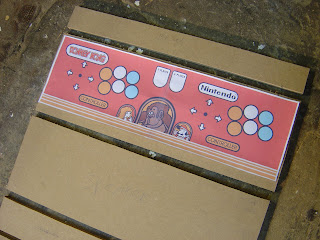
I put a printout of the new Control Panel Overlay concept on the cut MDF, just to see how it would look.


From left to right:
Bottom, coin door, piece between coin door and speaker panel, speaker panel, control panel, bezel piece, marquee bottom, marquee back (where fluorescent light is attached to) and the top of the cabinet. Phew. For the back I have get a new sheet of MDF, but that can wait.

Meanwhile, I was working on a custom 2-Player Control Panel Overlay (CPO). I got a vector image file (Adobe Illustrator / CorelDRAW) of the replicated original Donkey Kong CPO from www.localarcade.com which I altered a bit to get to my concept. Had to add an extra joystick and a dozen extra buttons since I want to make a MAME arcade cabinet. I tried to keep it close to the original. Just watching at the new CPO design makes me smile, it's going to look good :)


Above: Original CPO (Without black instruction card on the left)
Below: New CPO!

Tuesday, February 5, 2008

Sanding the sidepanels

Just finished smoothing the sides of the cabinet with an electric sander. Now they are as even as a can get them - without a router that is. Seems you're better off using a router which enables you to make an exact copy of one cut out panel onto another one. Well, I'll keep that in mind for future projects then.


Looking better already huh? Next up, measuring and cutting the other cabinet pieces. Top, marquee platform, monitor supports, control panel top and front (with speaker), coin door, bottom and back. Should be less time consuming than the two just finished side panels because the other parts are all rectangular.

And! I ordered the Donkey Kong marquee, bezel and white Nintendo T-mold today! Very exciting. Once I'll recieve the marquee I let color-match the Donkey Kong blue from the logo to use the exact same on the cabinet.


Above, the marquee. The plexiglas piece with artwork on top of the cabinet. A fluorescent light has to go behind it so it lights up nicely.


Second, the bezel. Again a plexiglas piece that stands in front of the actual monitor. In this case smoked plexiglas (dark color). The game behind it lights up well but everything else (monitor casing, inside cabinet) should be blacked out with this screen in front. And hey, look at the sweet original artwork.


Then the T-mold. A plastic strip attached to the front side of the sidepanel to make them more durable and give it a nice finish.

When all installed it should look very much like this original Donkey Kong machine.

Sunday, February 3, 2008

Cutting the side panels

After a little test run it was time to cut the side panels with the Jigsaw. I did one panel a time. When the first one was done, I traced it on the second panel of MDF (15 mm or 5/8" thick). It went surprisingly well. Ofcourse they are not exactly even but I'll have to sand them anyway. But that's up for tommorow, first I have to buy some clamps to hold the two in place so I can sand them together for the best result.


A pity I didn't stand next to the panel on the sideview photo. Else you would see it's actually a pretty small arcade cabinet that I am building. Unlike the more modern ones.


This part above needs the most sanding. Cut a little too deep in the upper panel (top right). And bottom left is not very even with the original (top) panel.


Saturday, February 2, 2008

Done tracing!

Finally, after hours (really!) of calculating, tracing, erasing and calculating and tracing again - I'm done with the side of the cabinet! The measurements of the cabinet plan I got were in inches, so I had to convert them into centimeters first. But now it's all done. Let's hope I can jigsaw it out nicely so I don't have to do it all over.


The dark lines are from the eraser. Somewhere in between you'll find the proper tracing.


Couldn't have done it without the cabinet plan provided by www.jakobud.com


Very happy with the result. Looks even tighter in real life!

Friday, February 1, 2008

Building a test control panel

With the control panel (CP) parts i'd ordered (pushbuttons, joysticks, wiring and I-PAC) my brother and I started building a test panel. Stripping wires first and then attaching the crimp connectors. So no soldering required, easy! With a 28mm drill I made some holes in the board to stick the buttons through. The joystick I use now is an easy-mount stick (E-Stik). Not super fond of it but it mounts very easy - just like a button. Luckily, I have a couple of Happ Competition joysticks waiting for the final CP.


Top of the test CP. After playing with the buttons they seem too far apart and not really aerodynamicly set up. But hey, it's just a test panel.


The wiring doesn't look like we did a very good job. But in fact, if we'd tierap it, you could see it's actually properly done!